![]()
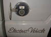
Solectria E-10 Restoration
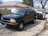
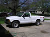
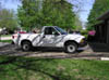
On Friday March 16th 2007, I won an auction for a 1996 Solectria E-10.
On Sunday March 25th 2007, I was able to arrange a pickup time, and went to Chicago to get the Truck.

Using a tow dolly, (my Blazer did not have the towing capacity to haul a vehicle transport, with the truck on it) I was able to get it back home with no problems.
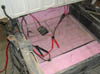
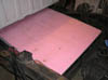
The truck had been sitting for 2 years, so I was a little worried about the tires (they are the original).
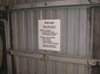
I did not have anyone to help get the truck off the tow dolly... so while thinking of a way to accomplish that, I glanced at one of the safety notices on the tow dolly and it gave me a good idea...
I set the parking brake on the truck, un-strapped it, put down the ramps, and then drove my Blazer out from under it, exactly what the safety notice said not to do.
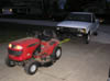
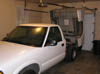
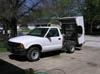
I then used my lawn mower to tow the truck into the garage. I was impressed how much torque it could generate in 1st gear.
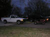
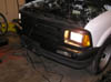
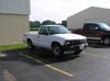
Both my new (11 year old, used, non-working) truck, and my 2001 Blazer in my garage.
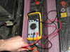
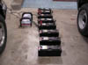
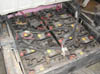
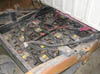
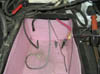
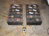
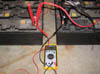
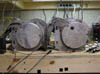
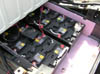
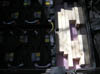
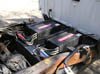
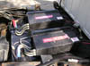
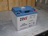
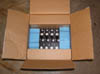
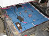
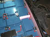
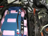
I then did a quick spot check on the batteries in the truck, to see if they where any good. They had not been charged in at least 2 years...
Some of them looked ok, but most where in really bad shape. The voltages ranged from 4.2 Volts to 12.5 Volts.
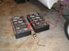
They are also EV1 batteries, not the correct batteries for this truck, nor was there any interconnect wires, they where just sitting in the battery boxes, and in the bed of the truck.
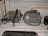
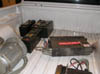
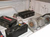
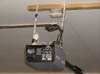
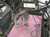
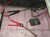
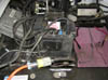
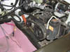
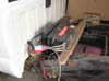
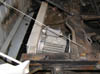
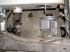
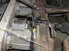
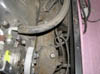
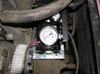
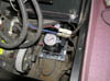
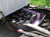
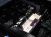
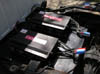
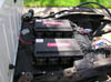
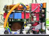
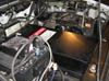
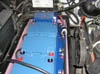
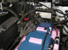
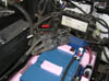
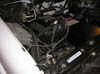
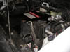
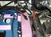
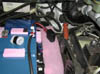
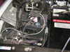
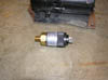
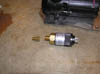
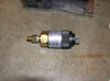
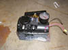
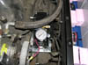
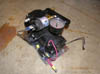
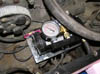
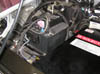
A quick check under the hood showed that I had the battery charger, and the power steering pump, motor and controller.
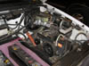
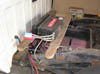
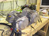
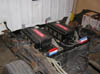
Both motors and controllers and some of the batteries where sitting in the bed of the truck.
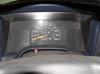
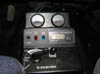
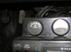
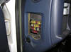
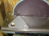
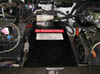
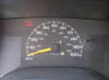
Only 8528.9 original miles. This Truck never had an internal combustion engine in it. It was purchased by Solectra as a rolling chassis. They then put in all the electronics and traction drive in. Note that the other gauges have been removed, and covered up with black tape.
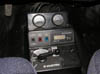
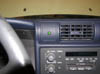
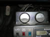
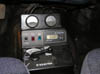
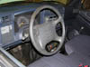
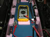
The important gauges are located on the center console: Volts, Amps, Amp-Hour counter.
There is also controls for the heater and AC.
The most important control is the forward/reverse and power setting switch.
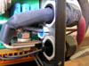
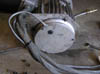
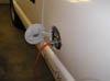
Under the gas cap, is the plug for recharging the truck.
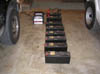
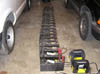
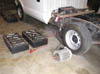
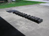
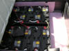
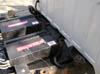
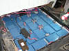
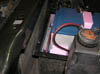
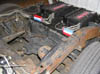
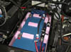
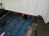
The next day, I took out all the batteries in the truck bed and the batteries in the front battery box. I then started to recharge each battery on its own to see if any where good enough for systems testing.
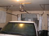
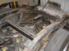
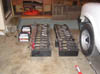
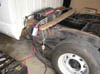
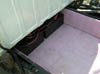
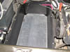
I then took out the motors and the controllers out of bed. With the bed empty, I could then lift it up to get at the batteries in the rear battery box.
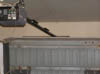
With the bed raised it came very close to hitting my garage opener. So I unplugged it, so I would not accidentally collide with the truck bed.
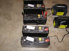
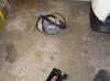
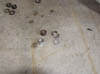
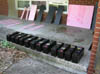
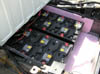
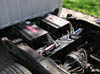
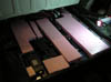
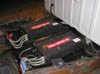
Batteries... lots of batteries.
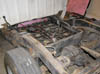
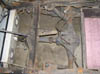
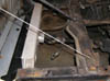
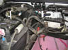
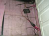
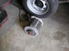
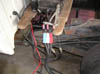
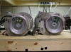
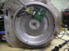
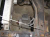
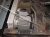
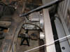
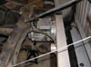
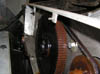
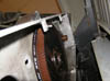
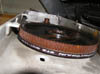
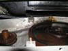
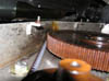
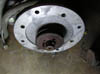
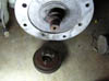
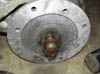
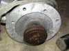
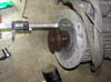
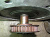
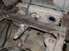
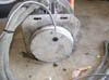
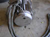
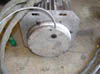
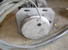
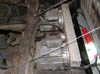
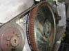
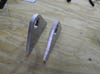
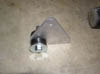
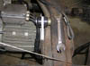
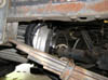
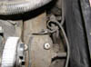
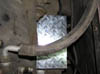
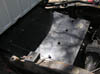
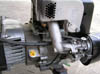
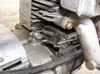
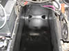
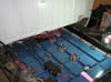
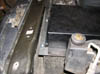
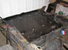
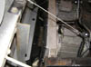
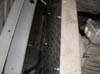
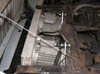
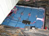
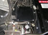
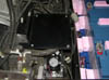
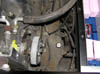
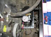
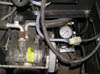
Because the batteries are heavy... I took some pics of the drive train. The differential is not a stock Chevy rear end. It is some kind of quick change rear end. It has been flipped over, such that the drive shaft goes away from the front of the truck. The drive shaft then goes to a large cogged belt pulley.
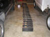
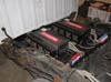
After a few hours, all the batteries where taken out of the rear battery box.
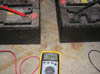
Over the next week, each battery was charged, and marked whether it was good or bad.
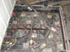
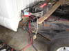
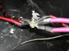
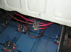
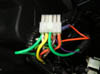
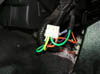
On Friday March 30th 2007, I started to connect all the connectors back together, for some reason every connector was unplugged.
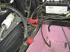
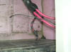
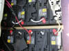
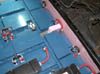
Next I taped up all the battery cables to keep them from shorting out on the truck frame.
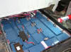
Of the 24 batteries that came with the truck, I was able to get 16 of them to hold a charge.
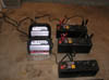
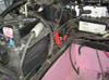
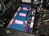
I then connected 12 of the batteries up in series using only 14 AWG wire. This was just encase something was shorted, it would just burn up the wire on the batteries, nothing in the truck.
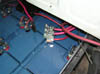
With the battery stack at 154 Volts I was ready to start testing systems in the truck.
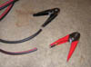
Next I connected the jumper cables to the battery stack. There was a huge spark, but nothing caught fire, or started smoking.
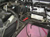
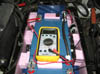
I then plugged in the battery charger, to see if it would see if it would work.
It came on and started to charge the batteries, for a little bit, then turned off with the green LED lit.
The green LED on the dash of the truck was also lit, so the charger thinks battery must be fully charged.
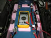
The Amp hour meter came on, as well as the Volt meter... Although the Volt meter reading is 10 Volts off.
I turned the ignition key and nothing else came on in the truck, I then tried the head lights and they worked.
At this point the The DC-DC converter was functioning, taking the main battery stack and converting it to 12 Volts to run all the regular Chevy S-10 electronics.
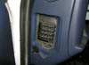
I then checked the fuse block on the truck, and was surprised to see that some one took out all the fuses. Which is why nothing else was working.
The next day, a quick trip to the local auto parts store yielded a Chevy S-10 replacement fuse kit. I disconnected the main battery and then plugged in all the fuses according to the fuse placement chart on the cover.
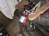
With a turn of the ignition key the power steering motor came on.
Its hard to see it moving in the picture, so here is a video of it.
The Amp-hour meter, was actually displaying that energy was being used, so it was working too. I was happy.
Everything powered by the DC to DC converter was now working, radio, turn signals, windshield wipers, horn, etc...
Next, I disconnected the main battery and took one of the controllers and wired it up to the truck.
Then, I plugged in a motor. Eager to see if it would spin...
The main battery was then reconnected, I turned on the key, flipped the switch to drive (max range).
I pressed the accelerator and the motor started to spin... here is the video
I then flipped the switch to reverse and the motor changed directions and ran fine.
I then hooked up the other controller, (it was missing the Anderson Power Pole connectors) It also spun the motor forward and reverse with no problems.
Next I connected the other motor back to the first controller, since it had connectors on it.
It would not commutate correctly forward, but worked fine in reverse.
So I swapped a phase and then it worked fine forward...
But it failed to commutate correctly in reverse... here is the video
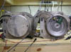
The next day I took off the covers of each motor, and found that one motor was wired as DELTA and the other motor was wired as WYE.
Thinking that this could be the problem why the motor did not work properly, I ohmed out both control cables I found my controllers where configured to dive DELTA wired motors.
I then re-wired the WYE motor into a delta motor.
After re-wiring the motor, I hooked it back up and it still did not commutate correctly in one direction. So I figured it must me something wrong with the encoder...
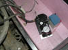
In the mean time, I noticed a connector was broken on one of the motor controllers, so I glued it back together.
On Tuesday April 3rd 2007, I took both motors down into the basement.
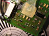
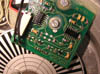
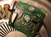
I took off the encoder covers to see if there was anything wrong with the encoder boards.
There are some surface mount LEDs on the encoder boards that light up in quadrature encoder sequence... however one was different then the other... but it turned out, that the LEDs where installed backwards on one of the boards.
I unsoldered the LEDs and turned them around and soldered them back on the encoder board, I figured the good motor was correct.
On Saturday April 7th 2007, I really dug into fixing this motor computation problem.
Fixing the LEDs was for display purposes... however the LEDs must be used to line up the encoder board, since you can't see the LEDs unless you take the back cover off. But I don't have the procedure to do that, so I had to use trial and error.
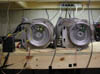
The first thing I did was line up both motors and wrapped a orange string between them, such that when you move one motor it moves the other.
Then I rigged up a battery and a cable to power the encoder boards, so I could look at the signals on the scope.
Here is a video of the encoder signals on the scope. The top two traces are the AB encoder signals from the good motor, and the bottom two traces are the AB encoder signals from the bad motor.
Note: the signals look odd, because they are differential, and I do not have enough scope probes to hook them up properly... however the tops of the traces are what is important.
In the video, I first rotate the motors forward, you can see that the traces all look good showing the correct quadrature encoder sequence. I then spin the motors backwards, you can see the A signal (third trace down) on the bad motor starts to disappear... This was the problem. With out the correct encoder position the controller does not know where the rotor is to commutate it.
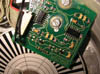
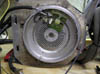
I then scraped off all the silicone and unbolted the encoder board and inspected the IR transmitters and receivers. They looked ok and not blocked by dust or anything.
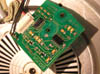
Next I put the encoder board back on the motor and started to adjust it. It is spring loaded, and there is enough play in the mount holes that it can move left/right, up/down, and in/out.
Using the scope I eventually got the encoder board lined up correctly so that it produced the same signals as the good motor.
Here are the good encoder signals video
Now happy that the signals looked the same, I was ready to secure the encoder board in place. Using the good motor as an example I siliconed the encoder board into place.
Then using more silicone, I put both the encoder covers back on the motors.
Both motors read to go back into the garage for testing.
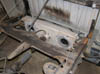
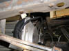
On Friday April 20th 2007, Now that both motors where working properly, it was time to install them.
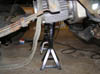
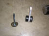
Motor, mounting hardware, and the jack... cause the motors are heavy.
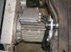
Motor jacked into place and then supported by a jack stand...
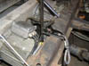
Then loosely secured with the mounting hardware...
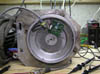
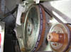
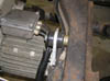
Next the belt was installed, this was a little difficult, since the large cog pulley had rusted a bit, so the teeth on it had slightly expanded. A bit of oil on everything helped it out.
The motor was then slid over, to tension the belt, then secured with the mounting hardware.
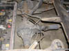
The other motor was more of a pain to install, because there should be a left and a right hand motor. I had two right hand motors (some where out there is another E-10 that has two left hand motors).
The first thing I needed to do was move the pulley out, so that it would not collide with the other motor's belt. Using where the other belt was tracking on the large cog pulley, I figured out how much I needed to move the motor pulley by.
Next I took out all three hex bolts, and then threaded them into the other three holes. By turning each one a little bit, eventually they will pop the pulley off the shaft.
Then the pulley was moved, to the new location and the hex bolts where moved back into the original holes and retightened to secure the pulley.
Next I lined up the motor to install it... but then I noticed that the mount holes on the back of the motor did not line up.
The next day, I took off the back motor mount off, and broke a few washers in the process.
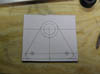
I then created a template out of cardboard to figure out how much I needed to rotate the back motor mount.
With the template on the motor, It looked like the plate needed to flipped over... but, since one end is bent, I needed to drill holes in a mirror image on the plate.
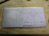
Next I made another template and transferred the new hole locations to the plate.
With some drilling and some filing, I now had a left hand back motor mount plate.
The new motor mount plate installed.
Motor jacked into place, and loosely held into place with the mounting hardware.
Both belts correctly tensioned.
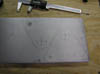
On Friday April 27th 2007, I started to make the back motor mounts.
Because I did not have the actual motor mounts, I used the dirt "shadow" on the motor plate and then did a bit of measuring to calculate the length of the mount based on the angle of the motor mount plates.
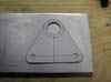
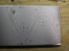
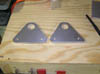
Using my measurements and some already acquired rubber shock mounts, I was able to come up with the following motor mount template.
Luckily work had some aluminum stock that was the right thickness for the rubber shock mounts. I transferred my template to the aluminum.
The future holes got center punched...
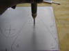
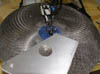
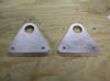
I then drilled out the large hole for the shock mount...
Next I flipped the plate over and finished drilling the first hole.
Ready to drill another one...
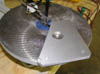
Testing how well the shock mounts fit.
Holes drilled for the motor side bolts.
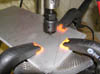
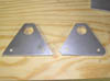
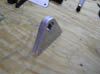
Now the hard part, I don't have a band saw yet... So I used my scroll saw with a hacksaw blade in it.
It actually did not do to bad of a job. The edges where smoothed down on my disc sander.
The next day, I began to install my newly fabricated motor mounts...
My motor mounts in all there glory.
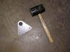
Using the "persuader" the shock mounts where beaten into the motor mounts.
I then installed the motor mounts to the frame rail and then the motor.
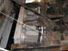
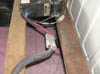
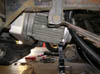
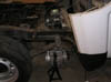
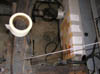
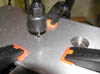
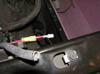
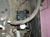
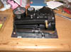
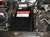
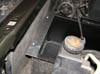
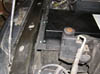
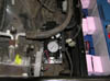
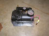
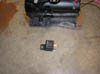
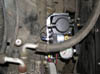
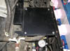
My truck was also missing a critical part, the vacuum pump needed to run the power brakes and some of the accessories. I took out the battery charger and the plate that it was sitting on to get to where the vacuum pump should be located.
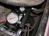
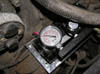
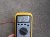
A quick test with my new pump showed that the vacuum system could hold 19 in-Hg.
I found the existing ground wire and power wire, (both had been cut), and put new spade connectors on them.
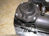
The vacuum pump I got had the vacuum port on the wrong side...
A quick disassembly and reassembly fix that...
Now the vacuum port was on the right side.
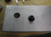
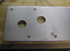
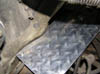
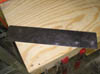
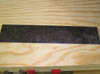
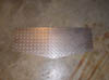
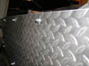
Next a made a made a mounting plate for the vacuum pump out of some left over 1/8" diamond plate.
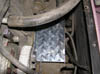
I cut it out so it would fit in nicely.
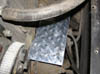
Then drilled some mounting holes in the plate.
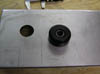
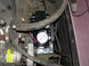
A quick check for any mount hole or clearance issues with the pump in place.
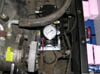
Next the vacuum pump was mounted on the plate...
And then it was installed in its new home.
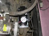
Next the pump was wired up and tested.
Then the mounting plate and the battery charger where reinstalled.
The vacuum pump happily running, and making sure my brakes work.
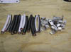
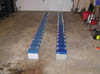
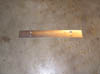
Next I built up 10 interconnect wires, made of 4AWG jumper cable I had laying around.
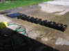
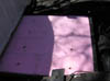
The next day, since everything was covered in dirt, and it was a nice day outside, I decided to power wash as much as I could.
I unwired my test battery pack, and moved them out onto the driveway, along with battery box covers.
I then pressure washed everything...
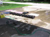
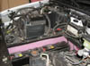
I figured as long as I was washing everything, I should wash the truck as well.
My right rear tire did not hold air very well, so I pumped it back up to make the truck easier to roll out in to the drive way.
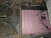
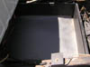
Next I rolled the truck out into the driveway and raised the bed.
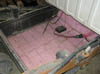
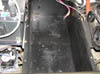
I pressure washed the exterior of the truck and the back battery box.
Meanwhile I moved all the other parts I had washed earlier over to the side of the house to dry out.

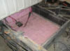
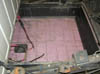
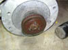
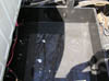
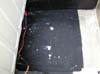
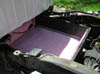
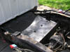
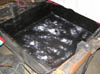
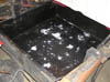
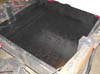
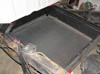
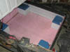
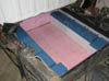
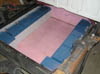
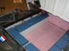
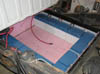
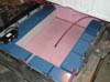
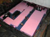
The bottom of the battery box was a bit corroded, there was actually a little bit of water in the battery box when I got it, this was due to all the drain holes, (one in each corner), being plugged up with dirt. I made a note that I should repaint them to keep them from corroding more.
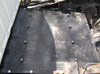
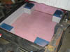
The battery box lining was put back in...
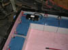
Next the insulation pieces...
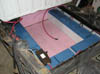
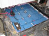
Then all the batteries...
All the batteries where wired in series, with the exception of the 100 Amp fusible link.
The 100 Amp fusible link was then installed, if anything caused the pack to short out, this would blow.
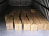
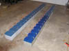
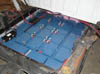
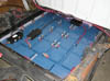
Because the batteries are not actually the right ones for this truck, I filled up the rest of the space with scrap 2x4 wood pieces.
Next the insulation cover and then the battery box cover where installed and bolted down.
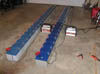
Then both motor controllers where installed and bolted down...
Next the 3 phase motor cables and the encoders where plugged in.

Then the frame ground wires, they let the controllers activate the brake lights when regenerative breaking, since there is no electrical connection between the main battery pack and the frame of the truck. (All the high voltage systems are electrically isolated from the low voltage systems.)
Next main power is connected to both controllers...
Then the drive command cables are plugged in.
One final check that everything is wired up and then the bed is lowered, and the truck is ready for its maiden voyage around the block...
I should have video the maiden voyage around the block a few times... but I was busy making sure I did not hear any bad sounds or see smoke coming out of anywhere...
I tested out the breaks, and they worked fine, the vacuum pump was doing its thing.
After the maiden voyage, I then pulled the truck back into the garage and recharged it.
I checked all the connectors for any signs of arcing or melting, everything looked fine.
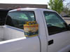
I was then ready for the first beer run...
Not knowing what kind of capacity the battery pack had, I decided that the first trip would be to go to the local grocery store and buy a six pack to reward my self for getting the truck all running again. This is about a 3 mile trip, with one large hill (highway overpass) in the way.
With the truck fully charged, I set out with the power setting on economy, which limits the controller current to 80 Amps.
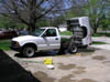
I made it all the way to the grocery store and got my beer... (while taking the picture a guy asked me why I was taking a picture of beer, I then explained everything and let him look under the hood, he was impressed.)
I went over to the gas station, which is a little bit down the road from the grocery store and put some air in my leaky tire, and then decided to take picture of the truck in front of the gas pump. The price of gas was around $2.49 a gallon as I recall, I should have gotten a picture of the sign (at the time of this writing, gas is around $2.99 a gallon).
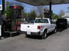
I then drove home and plugged in the truck to let it recharge, and enjoy my beer...
Total time to get the truck running:
Sunday March 25th 2007 - Sunday April 29th 2007
Approximately 150 hours of labor.
On Tuesday May 1st 2007
I continued to use the truck driving it around on short trips, trying to break the battery pack back in.
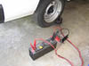
I decided that on Wednesday I would attempt to drive the truck into work. Just incase I ran out of power I made an adapter cable for my generator.
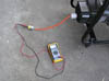
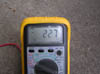
When I plugged my truck into the generator it would bog the generator down for a second and then the charger would turn off. I checked the voltage at the plug and under no load it was 227 Volts, but under load the voltage was dropping below 200 Volts.
I then adjusted up the governor to get it to output 240 Volts no load, this made the charger happy, it was dropping down to about 215 Volts under load.
On Wednesday May 2nd 2007
I don't have any pictures of this trip, since I forgot to bring my camera with me.
I drove to work taking country roads with the generator in the bed of the truck.
I would accelerate at 50 Amps up to 35 MPH, and once at 35 MPH, it only took 20 Amps to maintain that speed.
I was able to make it to work with no problems.
I then showed the truck to a bunch of people at work, most everyone knew I had an electric truck and wanted to see it.
I did not use the generator, because I wanted to see if the battery pack had enough energy to make it back, the Volt meter was showing 144 Volts.
I then set out on the trip back home, same rules: accelerate at 50 Amps up to 35 MPH and then maintain 35 MPH.
About 2 miles from my house the voltage had dropped down to 120 Volts, which is the limit for the controllers, they will not let the voltage drop below 120 Volts (this is to protect the batteries).
So I could only pull as much current as the batteries can provide, such that the voltage does not drop below 120 Volts.
About 1 mile from my house my max speed was about 20 MPH, but then I had to stop, which charged up the batteries a bit, so I was able to get back up to about 30 MPH, and then slowly start to slowdown.
I was able to make it back home, I then plugged in the truck to let it recharge.
My total trip used about 16 AH, which is 2.3 KWH (about 28 cents worth of electricity at 12 cents a KWH).
Total distance traveled was 20 miles, on average over the 40 minutes it took for the trip I was pulling around 24 Amps from the battery pack. Thus my battery pack was rated at about 20AH capacity at a C1 rating.
This means its definitely time for a new battery pack...
On Sunday May 13th 2007
I talked to work about the possibly of recharging... and they said it was ok, so long as they did not have to wire in anything special for it.
All the external outlets near the parking lot are 120 Volt and the truck says on it "220 Volt only"...
So, I took apart the battery charger to see how it worked and see if it could be modified to work on 120 Volts.
I got a hold of the data sheet for the charger and it turns out that it will work on 120 Volts, but at a lower efficiently and at less power.
On Tuesday May 15th 2007 (8,668 miles).
I had ordered 36 new batteries for my truck, so I needed to prepare it for the new batteries.
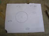
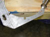
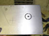
I was missing the front piece of lid of the battery box, so I need to fabricate one.
Front battery box installed, with a piece of aluminum to mark where the edges and holes would go.
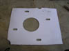
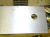
Marked and ready for cutting...
Cut to size and then drilled for the mounting bolts.
I needed to order some nut inserts so the battery box could screw into the part I just made.
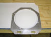
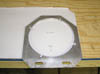
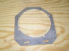
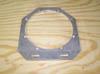
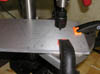
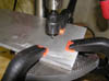
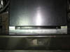
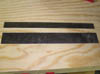
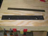
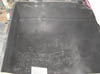
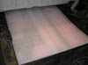
Also, the guys in the machine shop at work made a belt box cover plate on the sheer.
I also took all of the batteries out of the truck.
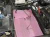
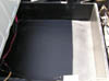
The next day, I cleaned out the front battery box and then took a paint scraper and scraped away all the bubbled paint from the galvanized steel corroding.
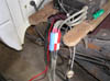
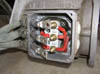
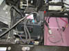
I took apart the main power distribution node to get all the wires out of the way, um... yeah I wire much better when I put it back together...
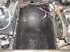
I then painted the inside of the front battery box.
Next it was more Scraping on the back battery box...


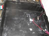
Then it got a fresh coat of paint.
The next day, I rented a trailer and drove to Chicago and picked up my batteries.
These batteries are rated: 42AH at a C20 rating, 40AH at a C10 rating, 38AH at a C5 rating, 25AH at a C1 rating.
I then created 2 stacks of 18 batteries in parallel, and then started to charge and equalize all the batteries.
On Saturday May 19th 2007
I had been using the truck to make small trips and errands on the old battery pack, and every once in a while I would get stuttering from the truck and regen cutting in an out, like there was a bad connection to the throttle pot.
I tracked it down to the IDC connector on the throttle pot to the center consol. The clip that held in the ribbon cable was broken, and no longer holding the ribbon cable on the connector.
I replaced it with a new one, and have not had a problem since.


The truck is supposed to have three 180 Amp 200 Volt fuses in it, one for each battery stack. I could not find any rated for 180 Amps and 200 Volts, but I was able to find some 250 Amp 200 Volt DC circuit breakers, designed for solar power installations, really cheep.
And since I was already planning on upgrading the 4 AWG interconnect wire to 2 AWG which can carry 250 amps for 1 second and my circuit breaker will kick out in much less then a second, it should be ok.
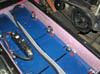
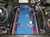
Front and rear battery boxes ready for batteries.
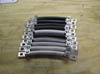
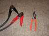
The next day, I cut up a nice pair of 2 AWG jumper cables...
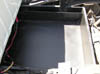
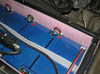
Batteries slowly made there way into the battery box. It was nice to see that they actually fit...
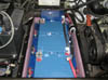
The circuit breaker... I later move it to the long cable that goes from the back battery to the front battery on the row...
More batteries...
2nd row of batteries...
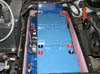
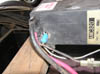
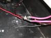
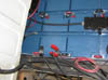
I did not like the angle wire on the right was bending, so I made an extension and wrapped it with electrical tape. I later enclosed the junction in a plastic box too.
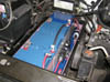
At this point I decided to move the circuit breaker to the longer cable that spans from the back right of the box to the front top battery.
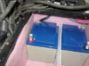
Little jumpers finish off wiring the front battery pack.
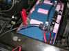
A final look at the front battery pack (A stack)...
Batteries, used to hold up the battery box insulation.
More batteries...
On Monday May 21st 2007 (My Birthday)... Yup. I spent it working on the truck.
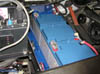
Left side wired...
Right side wired...
Circuit breaker wired...
All the batteries wired (B Stack).
Over night the batteries reproduced filling out the empty space...
And then they wired them selves...
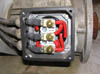
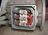
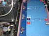
Next, I replaced that really bad power distribution node, with a nice big copper bus bar.
The next day, I filled up the gap in the batteries with some foam.
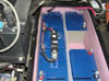
Everything now wired (C Stack)...
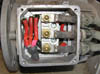
Temporary electrical tape and insulation around the main power bus...
More foam to take up the gap between the top of the batteries and the battery box cover.
More foam to take up the gap between the top of the batteries and the battery box cover and keep the batteries on the top from shifting around.
Plugging in the main system power connector (note each pin is labeled 'A' 'B' 'C').
Now that I new where the batteries would be, I could place the battery box lid on the and figure out where to mark and drill my front battery box holder, then persuade some nut inserts to become one with the aluminum.
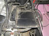
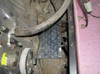
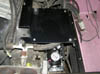
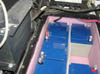
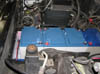
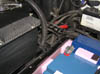
Gap where the new plate would go. (note, not a radiator, its the condenser for the air conditioner).
Front battery cover bolted to the plate...
Front battery cover installed.
Insulating the back batter box.
Back battery cover installed.
Motor controllers installed.
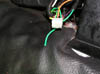
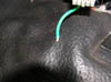
The next day, I found a wire to the center console that was broken...
It turns out that it was the one that went to the air conditioner switch. This could be the reason why my air conditioner motor and controller are missing...
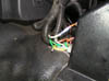
I took off the connector and found that none of the pins where crimped correctly...
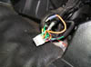
Using a pin extractor I borrowed form work, I removed each pin one at a time, cut it off and re-crimped and soldered a new pin on.
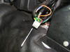
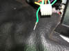
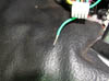
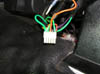
Look how bad this connector was.
Much better.
The next day, I finally drilled some holes and bolted in the belt box cover.
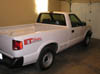
At this point in time the truck is pretty much done. There is only a few things left to do on it. I took a few pics to mark this point in the restoration...
On Wednesday May 30th 2007 (8,720 miles), I got new tires for the truck. Now I could go on the highway, and not worry about them exploding...
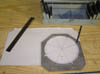
On Sunday June 3rd 2007 (8,818 miles), I performed a field discharge test. This is where you drive a bunch and then leave the lights, and heater on, and measure all the voltages on the batteries under load.
I took off the battery box covers...
And then measured all the voltages on the batteries.

All the batteries in A stack where fine around 12 volts, with the exception of one battery which was at 11 volts, it was also warm.
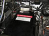
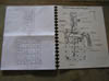
I wrote down all the battery voltages on a sheet of paper (I know the date on it says 06-02-07, that's cause I wrote down the wrong date, my camera has the right date on it, and it date and time stamps all these pics).
All the batteries in C stack where really close to each other, but there where 5 batteries in B stack that where not reading the same as the others.
I marked all the under performing batteries, and then recharged them individually.
Later, when all the batteries where fully charged, I swapped the bad battery in A stack with a good one from B stack.
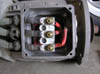
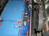
While I had the battery box cover off, I changed temporary wiring insulation covering, with a plastic enclosure...
Same with the main power distribution node.
On Saturday June 9th 2007 (8,942 miles), I did another field discharge test and found that the same batteries where still under performing.
I called up the battery company and showed them my data, and they sent me 6 more batteries for free.
I have not had any problems with the batteries since...
On Saturday June 16th 2007 (9,067 miles), I finally got all the parts needed to add a vacuum controlled switch to the vacuum pump, so it would not run all the time.
First, take out the battery charger...
Then, the mount plate for the battery charger...
Wait, can't get to the bolts... take off the front battery box cover...
Then, the mount plate for the charger...
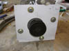
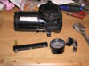
Finally, take out the vacuum pump.
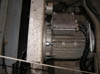
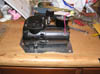
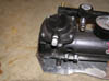
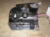
The vacuum pump in all its glory...
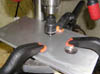
The pump is a little on the noisy side, so I added a stainless steel sintered muffler to it. This makes the pump 40db quieter.
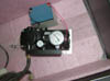
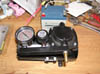
Here is the vacuum switch its adjustable from 1 to 30 IN Hg...
1/2" to 1/4" NPT Adapter...
Adapter, and switch ready to be installed on the pump...
Vacuum switch mounted on the pump.
Clearance check...
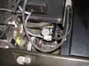
The vacuum switch was not rated to carry the 8 amps the vacuum pump can draw, so it actually turns on and off a relay, which actually turns on and off the pump.
Relay and switch wiring.
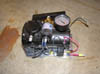
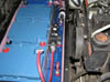
Everything wired back in, and vacuum line connected.
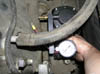
Vacuum switch test, the pump runs and then shuts off when it reaches 19IN Hg.
Battery charger plate back in...
Battery box cover back on...
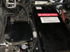
Charger back in... I also did not like the wires that where floating around the charger, so I wrapped some expandable sheathing around them.
Some people might notice that I have an air conditioner compressor, but no motor or controller so spin it... yeah, I am working on that...
On Friday July 27th 2007 (10,000 miles), I hit 10,000 miles on my way to work.
Winter 08 (15,312 miles), Fixed some intermittent propulsion issues.
During the Fall of 2008, I was having intermittent problems with the motors and controllers. Such that some times they wanted to work and some times they did not.
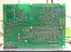
There is a programming / monitor port on the inside of the AMC320 motor controllers. I wanted to modify my controllers so that this port would be exposed and allow me to monitor the inputs to pinpoint what connection was intermittent.
During the Truck's winter down time, (It gets really cold in Illinois during the Winter. My batteries don't perform that well below freezing, and the electric heater does not help much either, oh and the salt used on the roads will eat the truck), I under took this task...
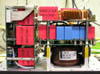
Soon to be modified AMC320 controllers.

Connector cover plate removed.

Hidden programming / monitor connector exposed. Its the DA15 connector on the right.

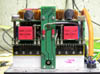
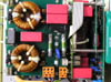
After taking the cover off and seeing how nice and shinny the connectors on the inside are, I decided to replace all the rusted connectors... I had to take them off anyway to drill out the plate for my new cable.


Connector cover plate free from the cables.

After getting the part numbers off of the old connectors, I was able to order all the exact same replacement parts.

Measure lots...


Drill once...

Well actually, twice.

Starting with a new round shielded ribbon cable. Stripping insulation and pulling back the shield.


Trimming off the excess ribbon cable, and covering the end with electrical tape.


Aligning the new DA15 ICD connector, and pressing it together. They do in fact make really expensive tools to do this, but a vise works just as well.


Installing the new connector in to its new shielded enclosure and soldering the shield wire to the enclosure tabs.


Plugging in all three connectors to the controller.


Reinstalling the cover plate on the motor controller.


New connectors installed using the same procedure as before.


The same was done for the other controller.

When I installed the motor controllers back in the truck, the old rusted connectors on the truck side just had to be replaced.


Everything hooked back up, nice and shinny new connectors.


August 2009 (17,600 miles), Started work on getting the truck Air Conditioning functional.
Initial
parts:
180 Volt, 7.5 Amp, 4000 RPM, 2.5HP treadmill motor.
Gates HTD 5mm tooth spacing x 15mm wide x 500mm long belt.
Gates HTD 22 tooth pulley.
5/8" TranTorq Bushing.
1/4" aluminum plate.
Solid state relay... Later replaced with a Kilovac EV200.

The motor has a 5/8" keyed shaft on it... I could drill a 5/8" hole in the pulley, but I have no way to cut a key way into it. So I had to use a TranTorq keyless bushing.
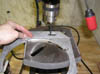
Next I found the smallest pulley that I could drill out and have it fit the TranTorq.
Since the TranTorq requires a 1" hole... And I don't have a 1" drill bit... I used a 5/8" drill bit and then a boring bar to make a 1" hole in the pulley.


Checking the fit of the TranTorq in the new 1" hole...


Checking the fit of the TranTorq and pulley on the motor shaft, perfectly centered.


The motor is designed to be side mounted, so I need to make a new mount plate that will convert it to a front mounted motor.


Marking for the new mount screws. There was only a small area to place the new mount holes, one on ether side of the motor bearing bulkhead.


In order to fit the motor into the drill press, the fan has to come off.


About to drill the motor face plate... With some tissue paper to prevent shavings from getting into the motor.


Tapping the newly drilled holes.


Testing the newly tapped holes. You can see in the second pic how much room there was for the screws.


Transferring the motor mount holes to the plate.


In order to adjust the belt tension, I slotted the mount holes.

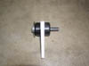
Fully assembled motor, with mounting plate and pulley.

Testing the fit in the truck.


Measuring how much play there is in the belt tensioning slots.


A piece of scrap aluminum is tasked to hold the electronics...

Using the motor's original mount as a template, holes are drilled.


Using the Kilovac as a template for its mounting holes. The other holes in the plate are for a solid state relay... The solid state relay worked fine, but was replaced with the Kilovac due to a horror story I heard about a solid state relay failing in a such a way that it shorted the higher voltage side to the low voltage control side... Which would be bad, very bad.


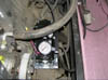
Kilovac mounted and wired.


Adding an extension to the relay that turns on with the air conditioning switch. This wire powers the condenser fan, and turns on the Kilovac.

Chassis ground for the control side of the Kilovac.

Everything mounted in the truck, with the belt nice and tight.


Initial system test. The motor was drawing 3.75 Amps. But it was not cooling anything...

I got an appointment
and took the truck over to shop and had them leak check and recharge the air
conditioning system with some more R134a.
They recharged it and could not find any leaks.
The motor now draws 6.29 Amps, and the air conditioning blows nice and cold.


April 2011 (21,676 miles), The cheep (made in China) AGM batteries reached end of life. I was only getting about 15 mile range out of them. They lasted 13,000 miles.
After looking at different battery options (Lithium-Ion was way to expensive) I decided to go with Gel Cells (made in America). Hopefully they last longer then the AGM batteries...
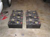
36 Old AGM batteries.


24 New Gel Cell batteries.

Old batteries removed.


One thing I did not like about the previous battery layout was having battery terminals hidden underneath the cab... So this time around I arranged them so none are hidden.

The new batteries are a bit taller, and don't quite fill out the battery box, so wood spacers are used to fill in the gaps.


Back battery box all wired.

Front battery box.


Front battery box wired up.

Since the batteries are taller, a spacer is needed so that the front battery box cover will clear the batteries.

The spacer was also used to hold the batteries in the center of the other batteries.


I had to use 1/4 20 threaded rods due to the added height of the spacer.


Back battery box covered up, motor controllers installed.


Last but not least... reprogramming the battery charger for Gel cells.

July 22 2013 (34,302 miles), Driving home from work on the highway, I noticed all of a sudden a large drop in pack voltage... I knew that I had lost half the battery pack.
When I got home, I opened up the front battery box, since it is easier to get into then the back battery box.
I was greeted by the smell of hot metal. The top of my battery box insulation was melted.

This battery connection was now an open circuit. One of the battery terminal connectors had cracked, resulting in a bunch of arcing, and oxidation of the copper bus wire.


Connections taken apart.


I think the connection failed because it was to stiff, and vibration from driving around caused the battery terminal connector to crack.
So I replaced the straight connection with a curved one, so that there was some some more flex between the batteries.

Since there where two other straight connections in the front pack (I looked at the pics on there of the back pack and did not see any of the same style), I preemptively replaced them.


All wired back up... with spacer.


Figured I should repair the hole in the insulation, with a little spray adhesive and some more sheet foam.


Front battery box cover back on.

So looks like 2 years, 3 months on the "new" batteries (12,626 miles) before one connection failed.
Things left to do on the truck:
Upgrade to Lithium-Ion batteries...
Add a solar array to the bed of the truck and design some maximum point power trackers...
Add an ultra capacitor and bi-directional buck-boost converter to supplement the battery pack...
More EV Projects